LIDAR data acquistion with a UAS
Introduction to LIDAR technology -Zenmuse L1
Author: Rohith Maben - Last update: 2023-08-31
Citation:
Maben, R. P. (2024). LiDAR data acquisition with UAS- DJI M300 RTK + Zenmuse L1. Zenodo. https://doi.org/10.5281/zenodo.11609515
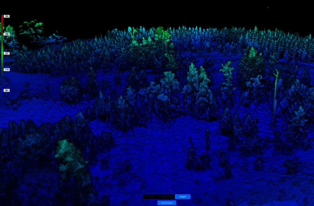
LIDAR stands for Light Detection and Ranging. The System mounted on an aerial platform comprises a set of instruments such as a laser device, an inertial navigational measurement unit, a high-precision GPS module, and data storage. The Inertial measurement unit measures the attitude vectors of the UAS. The laser device sends light pulses to a target and determines the range. The time between the emission of the pulse and the detection of the reflected signal gives the range. The following are the specifications for the L1 LIDAR used for point cloud capture:
General | |
Dimensions | 152 X 110 X169 mm |
Weight | 930 g |
Power | 30 W; max: 60 W |
IP rating | IP 54 |
Supported aircraft | Matrice 300 RTK |
Operating Temperature Range | -20 to 50 deg. Celsius RGB camera : 0-50 deg Celsius |
System Performance | |
Detection range | 450m @ 80% reflectivity, 0 klx 190m @10% reflectivity, 100 klx |
Point rate | Single return: max. 240,000 pts/s Multiple return: max. 480,000 pts/s |
System Accuracy | Horizontal: 10 cm @ 50 m Vertical: 5 cm @ 50 m |
Real time Point Cloud coloring code | Reflectivity, Height, Distance, RGB |
LIDAR | |
Laser wavelength | 905 nm |
Beam Divergence | 0.03 deg (horizontal) X 0.28 deg (Vertical) |
Ranging accuracy | 3 cm @ 100 m |
Maximum Returns supported | 3 |
Scan Modes | Non repetitive (NR) scanning pattern, repetitive scanning pattern (R) |
FOV | NR: 70.4 deg. (Horizontal) X 77.2 deg. (Vertical) R: 70.4 deg. (Horizontal) X 4.5 deg. (Vertical) |
Laser Safety | Class 1 |
Inertial Navigation System | |
IMU Update Frequency | 200 Hz |
Accelerometer Range | +-8g |
Angular velocity Meter Range | +-2000 dps |
Yaw Accuracy (RMS) | Real time: 0.3 deg, post-processing: 0.15 deg |
Pitch/Roll Accuracy (RMS) | Real time: 0.05 deg, post-processing: 0.025 deg |
RGB Mapping Camera | |
Sensor Size | 1 in |
Effective Pixels | 20 MP |
Photo Size | 5472 X 3078 (16:9), 4864 X 3648 (4:3), 5472 X 3648 (3:2) |
Focal Length | 8.8 /24 mm |
Shutter Speed | Mechanical shutter speed:1/2000-8s Electronic shutter speed: 1/8000 -8s |
ISO | Video 100-3200(auto), 100-6400 (manual) Photo 100-3200(auto), 100-12800 (manual) |
Aperture Range | f/2.8-f/11 |
Supported File System | FAT (<=32 GB); exFAT (>32 GB) |
Photo Format | JPEG |
Video Format | MOV, MP4 |
Video Resolution | H.264, 4K: 3840X2160 30p |
Detection range: Refers to the farthest measurable distance of the LiDAR. This parameter varies considerably based on the actual operating area. The main influencing parameters are the target's surface reflectivity, shape, and ambient light interference. In the case of DJI L1, its LiDAR supports a measurable range of 450 meters under 0 klx when the measured target's reflectivity is 80% and 190 meters under 100 klx when the target's reflectivity is 10%.
Scanning frequency: The scanning frequency is directly related to the density of discrete returns obtained. A high-frequency system can generate desired return densities by running on an aircraft that flies higher and faster than an aircraft carrying a lower frequency system, thereby reducing flying time and acquisition costs.
Scanning angle: Field of View (FOV), also known as the scan angle, represents the angle covered by the LiDAR sensor or the angle at which laser signals are emitted. The FOV of L1 varies in different scan modes. Repetitive scan: FOV 70.4 degrees X 4.5 degrees. The vertical field is narrower in this scan mode, but the accuracy is higher. This mode is recommended for high-accuracy surveying and mapping. Non-repetitive scan: FOV 70.4 degrees X 77.2 degrees. In this scan mode, the vertical FOV is wider. This mode is recommended for data-capturing complex structures, such as building facades.
Beam divergence: A divergence angle, if any, of the beams from the LiDAR can produce light spots that increase in size as the distance increases.
Auxiliary sensors: Auxiliary sensors are the navigation sensors necessary to determine the location and the orientation of the UAS and its remote sensors. For the UAS and onboard sensor position determination, the Global Positioning System (GPS) is used. For the attitudes or orientation of the UAS and the onboard sensors, the Inertial Measurement Unit (IMU) is used.
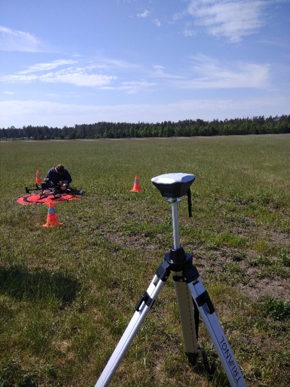
System specifications: DJI M300 multirotor and L1 LIDAR sensor
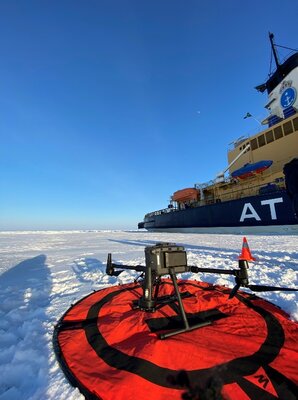
Author: Rohith Maben
Dimensions | Unfolded, propellers excluded :810 X 670 X 430 mm (L X W X H) Folded, propellers and landing gears included: 430 X 420 X 430 mm (L X W X H) |
Diagonal Wheelbase | 895 mm |
Weight (Batteries excluded) | 3600 g |
Max Payload | 2700 g |
Max Takeoff Weight | 9000 g |
Operating Frequency | 2.4000-2.4835 GHz; 5.725-5.850 GHz |
EIRP | 2.4 -2.4835 GHz; 29.5 dBm (FCC); 18.5 dBm (CE); 18.5 dBm (SRRC); 18.5 dBm (MIC) 5.725-5.850 GHz: 28.5 dBm (FCC); 12.5 dBm (CE); 28.5 dBm (SRRC) |
Hovering Accuracy (Windless or breezy) | ±0.1 m (Vision System enabled); ±0.5 m (P-mode with GPS); ±0.1 m (RTK functioning properly)
±0.3 m (Vision System enabled)); ±1.5 m (P-mode with GPS); ±0.1 m (RTK functioning properly) |
Max Angular Velocity | Pitch: 300°/s, Yaw: 100°/s |
Max Pitch Angle | 30° (P-mode and Forward Vision System enabled: 25°) |
Max Ascent Speed/Max Descent Speed (vertical) | 6 m/s; 5 m/s |
Max Descent Speed (tilt) | 7 m/s |
Max Horizontal Speed | 23 m/s |
Service Ceiling | 5000 m (2110 propellers, takeoff weight ≤ 7 kg ) / 7000 m (2195 High-Altitude Low-Noise Propellers, takeoff weight ≤ 7kg) |
Max Wind Resistance | 15 m/s |
Max Flight Time (Sea level) | 55 minutes |
Ingress Protection Rating | IP45 |
GNSS | GPS+GLONASS+BeiDou+Galileo |
Operating Temperature | -4° F to 122° F (-20°C to 50°C) |
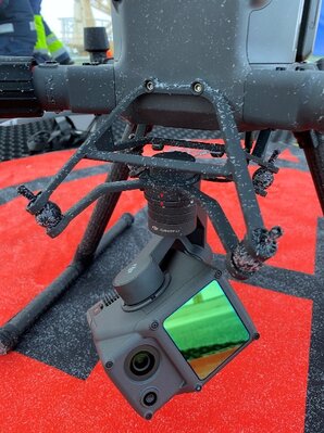
The LIDAR used for data acquisition onboard the M300 UAS is the Zenmuse L1. It integrates a Livox LIDAR module, a high-accuracy inertial measurement unit, and an RGB camera. This camera has a 1-inch CMOS sensor, and the package is mounted on a three-axis stabilized gimbal. The combination of using the DJI M300 along with the L1 sensor and the Terra software for flight planning and postprocessing provides a simplified workflow for any field work.
The L1's point cloud data rate is affected by which echo mode is used. Three echo modes are available: single-echo, dual-echo, and triple-echo mode. In single-echo or dual-echo mode, the maximum sampling frequency is 240 kHz (240,000 laser beams emitted per second). In triple echo mode, the maximum sampling frequency is 160 kHz. Theoretically, the maximum number of points measured per second in the dual-echo or triple-echo mode is 480,000. In practice, the number of points measured in the second and third echoes is minimal. The number of estimated points is the highest at a sampling frequency of 240 kHz in dual-echo mode. Therefore, it is recommended to choose the dual-echo mode if you need more measured points or the triple-echo mode if you need higher penetration.
Before flight mission execution
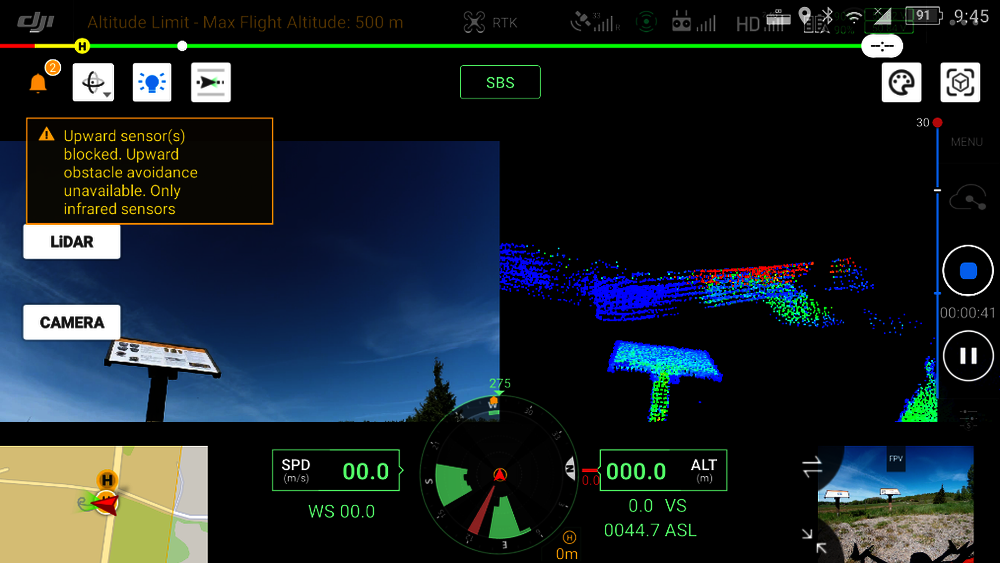
On the field, a few steps need to be followed to assemble the hardware for the flight. The Landing gear must be installed and locked in place. The L1 sensor is attached to the gimbal mounting hard point on the underside of the multirotor. Before the flight, the battery is installed with the safety pin in the correct orientation. The flight operator must ensure that the flight area is safe before each flight. The drone operator must always maintain a visual line of sight (VLOS) with the drone. The system has a Return to Home feature (RTH), so it can autonomously fly back and land at the home location. When the GNSS signal is strong, and the RTH button is pressed and held during a mission, the aircraft will stop the mission immediately and begin RTH. Users can resume the mission if required. When there is only sufficient battery power for RTH during a mission, the remote controller will alert for a few moments, the aircraft will pause the mission, and begin RTH. After replacing the battery, the mission can resume from the paused point. When using the drone with the obstacle avoidance feature turned on, check that the Sensing System is operational in the current surroundings. If it is not, disable it in flight planning software, or the flight may be adversely affected.
Workflow for data acquisition
Most data capturing is carried out in an autonomous flight mode to ensure consistency and repeatability.
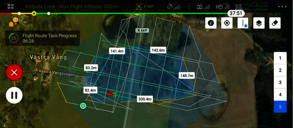
1. Area Planning: Enter the mission planning tab within the DJI Pilot App and draw the target area on the map. Due to IMU calibration requirements in every 100s, the mission must be planned considering the battery life. Regarding the recommended speed of 10m/s, a single flight route should not exceed 1000m (Multiple areas can be scanned separately in the case of a significant area data acquisition.)
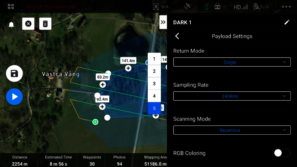
2. Select Camera: LIDAR payload DJI Zenmuse L1 for mapping The camera-specific settings can be accessed in the camera view option by selecting the camera. The camera parameters (ISO, shutter, and EV value) can be altered according to the operational environment.
With the general settings tab, the following parameters can be set:
Parameter | Value/description |
Camera type | Zenmuse L1 LIDAR Mapping |
Point cloud density | Number of points per sq.m |
IMU calibration | Enabled |
Altitude mode | Relative or ASL |
Flight route altitude | 50-100 m (<150 m to avoid data loss) |
Target to surface Takeoff Point | 0 |
Takeoff speed | User defined |
speed | 5-10 m/s |
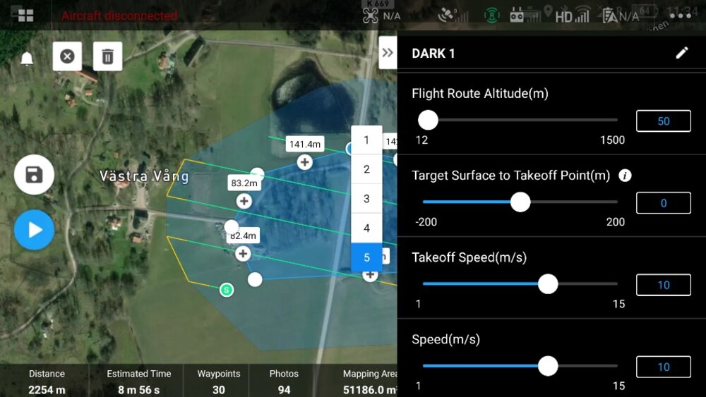
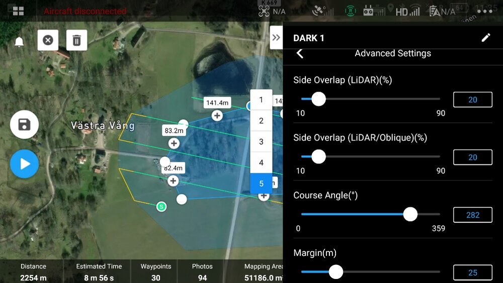
Within the advanced settings tab:
Parameter | Value/description |
Side overlap | Mission specific (50%) |
Course angle | Mission specific |
Margin | 0 or Mission specific |
Photo mode | Timed Interval shots |
4. L1 camera settings: the parameters of the L1 sensor can be set in the menu option. The recommended settings for manual flight mode are non-repetitive scan dual eco mode 240 kHz sample rate and RGB coloring turned on; the shooting interval is set to 3 seconds. The payload specific settings are described in the following table.
Parameter | Value/description |
Echo mode and LIDAR sample Rate | Triple Echo and 160 kHz for penetration.
Dual Echo and 240 kHz for maximum points. |
Scan mode | Repeat |
RGB coloring | On |
Troubleshooting
Care must be taken during the preflight sensor setup to avoid data corruption or loss of data quality. Some of the common issues with accurate data acquisition are:
- You are setting a low overlay value, especially in areas with many fluctuating terrains.
- The flight mission is started before the inertial navigation system completes warms up or IMU calibration is not done, resulting in low positional accuracy.
- Loss of positional accuracy due to the non-availability of RTK correctional data. This could be due to movements in the base station, the need for multiple base stations, or the lack of cellular connection to access network RTK.
Data storage:
In manual flight , the data collected consists of point cloud data and RGB images which are saved in the SD card located on the L1 sensor. The datafile is stored with the name : DCIM/DJI_YYYYMMDDHHMM_serial_number_XXX.
The LIDAR files on the SD card consists of the following:
CLC | LIDAR camera calibration data |
CL1 | LIDAR IMU calibration data |
CMI | visual calibration data |
IMU | inertial navigation data |
LDR | LIDAR point cloud raw data |
RTK | RTK main antenna data |
RTS | STK sub antenna data |
RTL | rod arm data |
JPG files | photo data |
*The missing .RTB file indicates that the RTK was available during the flight | |

